
What does a disc spring calculation estimate?
A disc spring calculation estimates the load-deflection relationship of a conical spring washer. In RFQ work, it helps both sides see whether the proposed geometry is close to the target before samples or production drawings are discussed.
It is not a certificate. A valve, flange, actuator or fatigue-sensitive spring still has to be checked against stress range, high-temperature relaxation, friction, guide clearance, surface treatment, seating condition and the cost of preload loss.
Core geometry and coefficient inputs
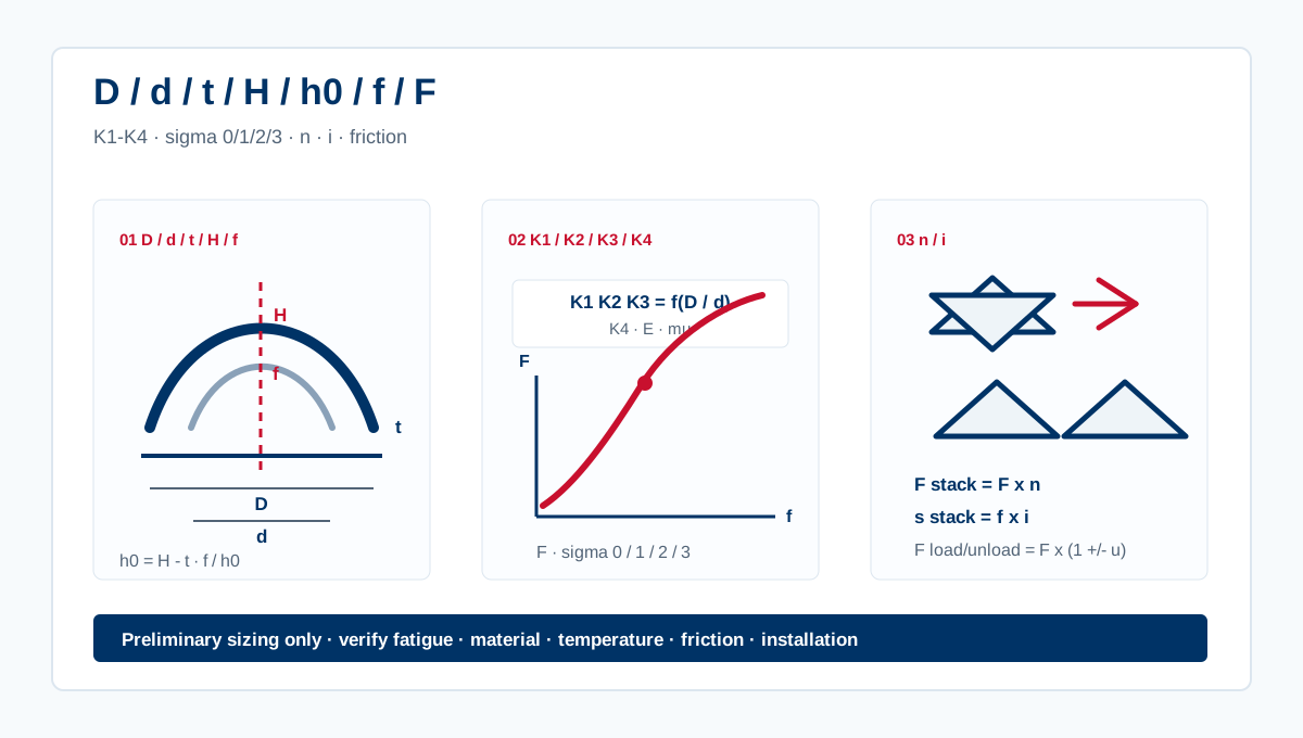
The usual symbols are D for outside diameter, d for inside diameter, t for thickness, H for free height, h0 for cone height and f for working deflection. Material inputs are elastic modulus E and Poisson ratio mu.
K1, K2 and K3 come mainly from the diameter ratio D / d. K4 corrects the result for geometry series, support edge or special design details. If K4 is not known, FeTech treats the result as a preliminary estimate rather than a released design value.
- D, d and t define the dimensional envelope and stiffness direction.
- H, h0 and f define the usable travel window.
- E and mu change with material family and can shift load output noticeably.
- K1 to K4 connect the geometry to force and stress calculation.
Single-disc force and stress checkpoints
For one disc spring, force is calculated from the material constant, diameter ratio, thickness, cone height and working deflection. The same geometry also gives stress checkpoints such as sigma om, sigma 1, sigma 2 and sigma 3.
Those stress points show whether the spring is being pushed into an unsafe deflection window. For cyclic applications, they are only the starting point; the load cycle, surface condition and material state decide the fatigue margin.
How stack calculation works
Stack sizing starts by separating force from travel. Parallel discs in the same direction multiply force. Series sets add travel. A quick preliminary stack force is single-disc force multiplied by the number of parallel discs.
The same logic gives a first estimate: parallel count n comes from target force divided by single-disc force, while series count i comes from target travel divided by single-disc working deflection. Both numbers still have to fit the available height and guidance.
- Parallel direction: higher force in roughly the same working deflection.
- Series direction: longer travel at roughly the same single-set force.
- Mixed stacks: tune force and travel together, then verify height and guidance.
Why friction allowance matters
Real stacks do not follow the ideal curve exactly. Friction appears between discs and at the seating faces, so loading force and unloading force can differ noticeably.
That difference matters in valve live loading and bolted joints because the available unloading force is what helps preserve preload after settlement. Final values depend on surface finish, lubrication, guide design and test data.
How FeTech uses the calculation in RFQ review
FeTech uses calculation as the first engineering filter, not the final promise. It helps show whether the geometry is close to the target load, whether the stack direction is realistic and whether the material family makes sense for the service temperature.
Before production, FeTech still checks drawings, material grade, heat treatment, surface protection, load target, installation height, cycle expectation and operating environment before recommending a DIN 2093 disc spring, Belleville washer stack or custom geometry.
أسئلة شائعة
How do you calculate disc spring force?
Disc spring force is calculated from outside diameter, inside diameter, thickness, free height, working deflection, elastic modulus, Poisson ratio and geometry coefficients such as K1 and K4. The result is a theoretical force-deflection estimate for one spring.
Does parallel stacking increase disc spring force?
Yes. Parallel stacking increases force because multiple discs share the same deflection direction. Series stacking mainly increases available travel instead of multiplying force.
Why is K4 important in disc spring formulas?
K4 corrects the theoretical result for geometry series, support edge condition or special design details. If K4 is unknown, the result should be treated as a preliminary estimate rather than a final design value.
Can an online calculator replace fatigue verification?
No. An online calculator can screen geometry and stack direction, but fatigue verification needs stress range, material condition, temperature, surface finish, cycle count and actual installation data.
هل تريد من FeTech مراجعة تطبيق النابض القرصي؟
أرسل الرسم ومساحة الرص والحمل المطلوب والحرارة والوسط والكمية. يمكن لفريقنا فحص اتجاه المادة ومنطق الرص وجاهزية التسعير.
- استبدال DIN 2093 أو هندسة مخصصة
- رص للصمامات والفلنجات والمشغلات والخدمة الشديدة
- مراجعة مواد الستانلس وInconel وHastelloy والتيتانيوم والفولاذ المقاوم للحرارة
الهندسة النهائية وعمر التعب ومصدر K4 والاحتكاك وشروط سطح الارتكاز تحتاج تأكيداً هندسياً.